Tag Archives: Firewalls

Cisco Zone-based Policy Firewall: Understanding the self zone

In the articles presented so far, we have studied situations in which inspected traffic is crossing the router-based firewall (instead of being directed to any of the router addresses).

The default operation of the Cisco Zone-based Policy Firewall (ZFW)  is to allow traffic to an from the router interfaces,  irrespectively of zone-pair security settings. If there is a need to modify this behavior, a system-defined zone, whose reserved name is self, must come into the scene.

Although interfaces are not directly assigned to the self zone, this special zone handles packets travelling from any router interface to a non-self zone (and conversely). You should keep in mind, though, that policies involving the self zone are still unidirectional.

Some facts about our reference topology are registered below:

  • The policy construction employs the classic building blocks. The only particularity is that one of the interconnected zones is the self zone.
  • The OUT-SELF zone-pair security is controlling packets sourced from the OUTSIDE zone and directed to the router interfaces. Packets originated by the router are not being inspected.
  • Policies involving the self zone are more meaningful when they include L3 restrictions (materialized by ACLs).
  • The activation of logging occurs in the same manner as already analyzed for non-self zones.

Inspecting router-bound traffic with the Cisco Zone-based Policy Firewall

** Topics for Study:

  • Make sure you understand the handling of IOS object-groups.
  • Revisit the post related to ACL integration into a ZFW scenario.
  • Construct a ZFW policy to control traffic originated by the router and destined to the OUTSIDE zone. You should allow only ICMP Echo and Echo Reply messages from interface F0 to the 172.22.22.0/24 subnet.
  • Update the ZFW policy analyzed in this post to limit telnet sessions going to the router. Telnet should only be allowed from sources located in the 172.21.21.0/24 subnet and directed to the Fo interface.
  • Review the articles related to logging in the ZFW series (both for dropped packets and connection setup/teardown).

** Related Posts:

Leave a comment

Filed under English, Firewalls, Security

HTTP Inspection on non-standard ports with the Cisco Zone-based Policy Firewall

The current post uses the ip port-map command as an auxiliary resource to enable HTTP inspection on the Cisco Zone-based Policy Firewall (ZFW).

In our reference topology HTTP is enabled on ports 2002 and 2003 for host 172.17.3.40. The ip port-map command simply instructs the router to treat these ports as HTTP and not as generic TCP. With this type of setup, any specific L7 configuration that applies to HTTP (on its default port) would equally be valid for the non-standard range of ports.

Inspecting HTTP on non-standard ports with the Cisco Zone-based Policy Firewall

** Topics for Study:

  • Play with the ip port-map command for other protocols. What is the default port for SIP ? And for MGCP ?
  • What is different in the audit-trail message in this example when contrasted to the connection logging messages for a single channel protocol like telnet ? (If needed, revisit previous posts in the ZFW series).
  • Does the ip port-map command apply to Context Based Access Control (CBAC) ?

** Related Posts:

Leave a comment

Filed under English, Firewalls, Security

FTP Inspection with the Cisco Zone-based Policy Firewall

Having analyzed the basic L4/L3 configuration  principles for the Cisco Zone-based Policy Firewall (ZFW), we will now illustrate some L7 options.

Before we start the practical examples, it is interesting to characterize the main usages of L7 inspection on a stateful firewall:

  • Fixing up misbehaved protocols, such as those that dynamically negotiate data connections inside the control channel. Classic examples are FTP and the telephony signaling protocols (SIP, H.323 framework, SCCP, MGCP).
  • Perform Network Address Translation (NAT) at the application level for those protocols that embed the IP address in the L7 messages. This is critical within NAT and Port Address Translation (PAT) environments.
  • Use the application knowledge to filter based on additional criteria pertaining to the specific L7 protocol, rather than just L4/L3.

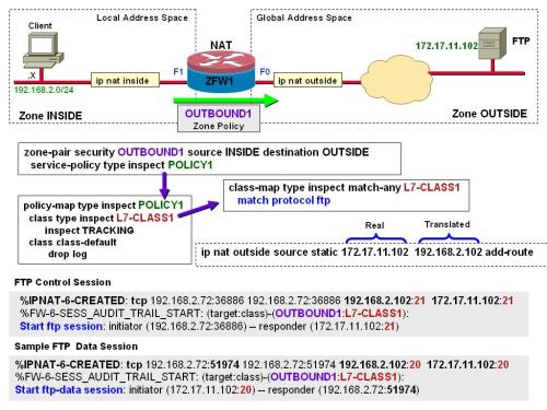
The figure depicts a reference scenario for FTP inspection on the ZFW:

  • The INSIDE client 192.168.2.72 starts an FTP session to the translated address of the server (192.168.2.102).
  • Instead of matching based on an L4 clause, there is a match protocol ftp statement under the class-map named L7-CLASS1.
  • The first audit-trail message shows the creation of the FTP control connection (over port TCP/21).
  • The second log message shows a sample FTP data session (and the corresponding NAT operation).

It is important to emphasize that in this sample network we are not performing any special filtering. We are just using L7 knowledge for fixup purposes.

Reference topology for FTP inspection with the Cisco Zone-based Policy Firewall
** Topics for Study:
  • Review basic FTP operations
  • What are typical commands (inside an FTP control channel) that trigger the setup of a data channel ?
  • It is important to compare these new audit-trail messages with those for single channel protocols that use TCP as transport (such as telnet in previous ZFW-related posts). What has changed ?

** Related Posts:

Leave a comment

Filed under English, Firewalls, Security

Basic Configuration of the Cisco Zone-based Policy Firewall in Transparent Mode

In previous posts we studied many aspects of the Cisco Zone-based Policy Firewall (ZFW) operation:

  • How the ZFW compares with Context Based Access Control (CBAC)
  • Building blocks of a Zone-based firewall policy
  • The default deny behavior of the ZFW
  • How to build a simple L4 policy with the Zone firewall
  • How to log connections and dropped packets a ZFW environment
  • Integration of the Zone firewall with Access Control Lists (ACLs)
  • How to integrate the ZFW with Network Address Translation (NAT) and ACLs

The next step in our series about the Zone-based Firewall is to illustrate a basic configuration for ZFW operating in transparent mode. If you are not acquainted with the basic concepts pertaining to transparent firewalling, please check the post: “Quick Review of Firewall Connectivity options: Routed Mode and Transparent Mode” [ https://alexandremspmoraes.wordpress.com/2012/01/19/quick-review-of-firewall-connectivity-options-routed-mode-and-transparent-mode/ ].

It is easy to observe in the reference topology that the building blocks for the zone-based firewall policy are identical to those already studied. The significant change has to do with connectivity and not with rule construction. The figure also registers an audit-trail message and the command used to verify established sessions.

Reference topology for the Cisco Zone-based Policy Firewall in transparent mode
** Notes:
  • The audit-trail message and the show policy-firewall session command clearly show that the connection initiator (10.5.5.1) and the responder (10.5.5.2) are on the same IP subnet.
  • As discussed before, we could add L3/L4 restrictions to the basic inspection policy.
  • The ZFW interfaces shown in the figure (F0 and F1) are assigned to bridge-group 1.
  • The IP address of the ZFW needs to be configured in a Bridged Virtual Interface (BVI). Specifically, interface bvi 1, to match the bridge-group number. It is important to emphasize, however, that this IP is not used as a gateway address when hosts on interfaces F1 and F0 need to communicate.
  • To interconnect this BVI with the other IP-enabled interfaces, you need to enable Integrated Routing and Bridging (IRB) on your Cisco IOS router. This is accomplished with the bridge irb and bridge 1 route ip configuration commands.

** Related Posts:

Leave a comment

Filed under English, Firewalls, Security

Quick Review of Firewall Connectivity options: Routed Mode and Transparent Mode

Before it can start enforcing access control policies between domains of trust, firewalls need to be inserted in the network topology. The two basic firewall connectivity options, Routed Mode and Transparent Mode,  are briefly examined below:

  • Routed Mode: in such an arrangement, the firewall works as a Layer 3 element (much like a router) from the perspective of hosts connecting to it. Each of its interfaces is assigned to a different logical subnet and the packets are conditionally routed between them. In the reference scenario, the inside interface has the IP address 192.168.2.2, whereas the outside uses the address 172.20.20.2. Considering that the hosts are interconnected by the firewall, machines on the inside need to configure the address 192.168.2.2 as their L3 gateway in order to reach outside destinations.
  • Transparent Mode: the firewall acts as conditional (transparent) bridge, forwarding frames between interfaces using Layer 2 information. In this case, the two interfaces represented in the figure are connected to the same L3 subnet and the inside hosts use the external router (192.168.1.1) as their gateway to reach outside destinations. The great motivation for this connectivity model  relates to the fact that the firewall can be inserted in the network without impacting the existent IP addressing scheme (which may be quite convenient in various situations).

    Contrasting firewall connectivity options: routed-mode and transparent-mode

A technical term may sound not so intuitive the first time you hear it. For example, during a presentation, a customer once told me that he did not understand why “his transparent firewall was blocking everything“. “After all, it was supposed to be transparent…”

I just registered this situation to emphasize one key point: the term “transparent” relates with “transparent bridging” (the basic bridging technology for Ethernet interfaces). It is used with connectivity in mind and does not imply less security.

Actually, as we will see in other posts, the construction of firewall policies is basically the same for transparent and routed modes.

** Notes:

  • Transparent mode is often called bridge mode. (Why ?)
  • A transparent firewall is sometimes referred to as a stealth firewall (because it is not used as an L3 gateway).
  • A transparent firewall is very interesting to add filtering capabilities between elements that require L3 adjacency. This is the case for two neighbor routers running an Interior Gateway Protocol (IGP) such as OSPF or EIGRP.
  • Another common use of a transparent firewall is in a multicast routing scenario. The firewall just bridges the multicast packets and does not participate in multicast routing.

** Topics for Study:

  • Do a quick review of transparent bridging technology
  • What is a Bridged Virtual Interface (BVI) ?

** Related Posts:


Leave a comment

Filed under English, Firewalls, Security

Deploying the Cisco Zone-based Policy Firewall with ACLs and NAT

After presenting the correct way of adding ACL restrictions to a Cisco Zone-based firewall policy, it is time to examine how Network Address Translation (NAT) interacts with a Cisco ZFW deployment. Our particular environment (Figure 1) actually contains a combination of stateful inspection, an L3 rule (ACL) and NAT.

To facilitate understanding, we start by briefly describing our reference scenario:

  • Inspection (controlled by class-map TOP-CLASS2) defines that only those application protocols carried over TCP are allowed from the OUTSIDE to the INSIDE zone.
  • The ACL2 access-list limits the source hosts (subnet 172.18.2.0/24) that can initiate inbound connections to the server 10.5.5.5.
  • The two previous conditions are united under the match-all class-map JOINT2.
  • The server address 10.5.5.5 is seen on the global address space (after source NAT) as 172.18.2.5.

Figure 1: Reference scenario combining Cisco Zone-based Firewall, ACLs and NAT

If you ever integrated Cisco IOS regular interface ACLs with NAT, you will notice that the ACL used by ZFW now refers to the real address of the destination host (instead of the mapped address). This is a critical change to be aware of.

Figure 2 provides further visibility for the topology under analysis, in the specific case of a telnet session initiated by the outside client (172.18.2.20) and bound to the translated address of the server (172.18.2.5):

  • The first Syslog message shows how the address translation is created.
  • The audit-trail log message highlights that the responder is 10.5.5.5 (real address), meaning that the ZFW process understands NAT.
  • The show policy-firewall session command confirms that the inbound connection is established with the real address (from the ZFW standpoint).

Figure 2: Details about the Zone-based Firewall, ACLs and NAT integration

** Topics for Study:

  • Think about the integration of a classic IOS interface access-list with NAT. What is the advantage of referring to the real address (as done by ZFW) ?
  • Revisit some other categories of IOS NAT (for instance, destination NAT and Port Address Translation). How can you display the active translations ? Can you have more than one interface configured with the ip nat outside command ?
  • Consider the integration of CBAC with NAT and ACLs. Does CBAC refer to the real address ?  Or to the mapped address ? (Why ?)
  • Rebuild the ACL shown in this example using the concept of object-group.

** Related Posts:

2 Comments

Filed under English, Firewalls, Security

Integrating ACLs with the Cisco Zone-based Policy Firewall

A previous article about the Cisco Zone-based Policy Firewall (ZFW) exemplified the construction of a simple L4 policy. Several other posts in the ZFW series underlined the fact that we cannot use interface ACLs in a ZFW environment (to avoid breaking the stateful inspection activities).

The current post builds upon our past discussions and documents the correct way of configuring ACLs within a zone-based firewall policy.

The focus of the policy structure depicted below is on the class-map called JOINT1, which specifies two simultaneous conditions that must be met for packets to flow from the INSIDE to the OUTSIDE zone:

  • Inspection happens at L4 for application protocols that use either TCP or UDP transport. This is governed by the class-map TOP-CLASS1, already studied in the article Building a simple policy with the Cisco Zone-based Firewall.
  • Restrictions that involve combination of source and destination addresses and L4 ports are imposed the extended access-list ACL1. This ACL is called by the match-all class-map JOINT1.
Sample Zone-based Firewall policy that includes an Access Control List
The figure also shows a simple Syslog message associated with the scenario. An NTP session from the host 172.18.1.10 to the server 172.18.2.20 was allowed by class JOINT1. This means that this particular connection was in accordance with both rules contained in this class.
** Notes:
  • The object-groups referred to by access-list ACL1 are those defined in the post ‘The use of object-groups in Cisco IOS software’.
  • There is no interface ACL in this setup. The ACL rules are taken care of as part of one of the building blocks of a Zone-based firewall policy. It is important to emphasize that this is the correct manner of inserting L3/L4 restrictions into a basic ZFW L4 inspection policy.
  • The log keyword cannot be configured as part of an Access Control Entry (ACE) that is used inside a ZFW class-map.
  • Newer releases of IOS allow you to list the existent class-maps and policy-maps with the show running-config class-map and show running-config policy-map commands.

** Topics for study:

** Related Posts:


Leave a comment

Filed under English, Firewalls, Security

Logging dropped packets with the Cisco Zone-based Policy Firewall

The previous post about the Cisco Zone-based Policy Firewall (ZFW) discussed how to log connection setup and termination. The current one will focus on making information about dropped packets visible (by means of Syslog messages). The auxiliary configuration element that gets the job done is the parameter-map type inspect that has the reserved name global.

Figure 1 brings a summary of the topology and associated ZFW policy employed in the posts so far.

Figure 1: Reference topology and associated ZFW policy

Figure 2 shows how to turn on the logging of packets dropped by the Cisco Zone-based Policy Firewall. Some points to be aware of:
  • This action of logging dropped packets is disabled by default.
  • The settings inside the global parameter-map apply to all the classes and are not available as options under the default or user-defined parameter-maps (which were analyzed in the previous ZFW post).
  • When a packet is dropped by the drop action under a class, the class name is registered in the Syslog message.
  • Syslog messages that represent packets dropped as a result of the default denybehavior (which was the subject of a previous post) do not contain a class name.

    Figure 2: Logging dropped packets with the Cisco Zone-based Policy Firewalls

 ** Topics for Study:
  • Compare the parameter-maps examined up to now: default, global and user-defined.
  • Contrast the tasks of logging connections and dropped packets in a ZFW scenario.
  • Make sure you understand the difference between class-based drops and packets dropped by the default-deny behavior of the ZFW.
  • Remember that the default and global categories of parameter-maps were introduced in Cisco IOS 15.X. Pre-15 releases used a different syntax to log dropped packets.

** Related Posts:

Leave a comment

Filed under English, Firewalls, Security

Logging connections in the Cisco Zone-based Policy Firewall

In a previous post, we learned how to build a simple policy with the Cisco Zone-based Policy Firewall (ZFW). The current post goes one step further, by discussing some connection logging tasks in a ZFW environment.

The feature in charge of generating the Syslog messages related to connection setup and teardown for the ZFW is named audit-trail, which, as can be verified in Figure 1, is set to ‘off’ by default.

To modify this original behavior in the sample scenario of Figure 1, we defined a new parameter-map called TRACKING and bound it to the  TOP-CLASS1 class-map, as part of the inspect action. (It is simportant to emphasize that  all the other settings of the Default parameter-map remained unchanged).

This approach of creating a customized parameter-map brings more flexibility to the deployment because you could have, for instance, another class-map without the audit-trail mechanism enabled.

Figure 1: Parameter-maps and the Cisco Zone-based Policy Firewall (ZFW)

Figure 2 brings two sample audit-trail syslog messages for a telnet session going from the INSIDE zone to the OUTSIDE. It also teaches how to display information about an active connection by means of the show policy-firewall session command.

Figure 2: Sample audit-trail messages for the Cisco Zone-based Policy Firewall

 ** Topics for Study:

** Related Posts:

1 Comment

Filed under English, Firewalls, Security

Building a simple policy with the Cisco Zone-based Firewall

This quick post is aimed at illustrating the relationships among the ZFW building blocks available in the Class-Based Policy Language (CPL). To achieve that, we will build a very simple ZFW policy that employs only L4 inspection.

Some important aspects to observe in the scenario of Figure 1:

  • The top-level class-map TOP-CLASS1 specifies that only UDP and TCP connections are allowed from the source to the destination zone. Any other traffic (such as ICMP, GRE or IPSec) will be blocked when trying to flow from the INSIDE to the OUTSIDE zone.
  • The inspect action in the TOP-CLASS1 class-map is in charge of creating the entries in the state table (for allowed connections) and handling return traffic.
  • There is no interface ACL in this scenario. It is important to emphasize that interface ACLs are not part of a ZFW structure because they do interfere in the return traffic, thus breaking stateful inspection. The correct way of leveraging ACLs will be covered in another post.
  • The reserved class named class-default takes care of dropping and logging the packets that do not fall in the definition of the TOP-CLASS1 class-map.
  • Given that ZFW policies are unidirectional in nature, no connections can be initiated from the OUTSIDE zone to the INSIDE. (Unless we define a second zone-pair security statement interconnecting the OUTSIDE to the INSIDE).
  • In the event you needed to add another internal interface to the environment (for instance F2), the basic requirement would be to assign F2 to the INSIDE zone. (All the settings in the OUTBOUND1 policy would automatically apply).
  • In this first example we are not worried about specific application protocols or IP address restrictions yet.

Figure 1: Sample ZFW Policy using only Layer 4 Protocols

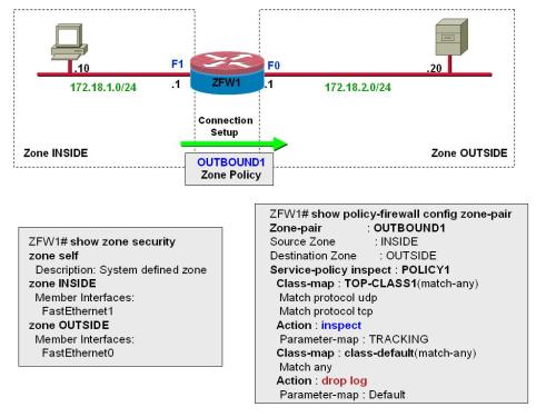
Figure 2 registers some important commands to verify ZFW policy structure:

  • The show zone security command provides information about the security zones already configured in the router. Notice that there is a system defined zone called SELF, which includes the router addresses. (Packets to and from the router on a ZFW scenario are handled by the SELF zone, which will be discussed in another post).
  • The show policy-firewall config zone-pair command summarizes the ZFW building blocks in use. It is a quick way of viewing the policy structure.

Figure 2: Viewing ZFW Policy Structure


** Related Posts:


Leave a comment

Filed under English, Firewalls, Security